


 12 / 164

8
Table 1
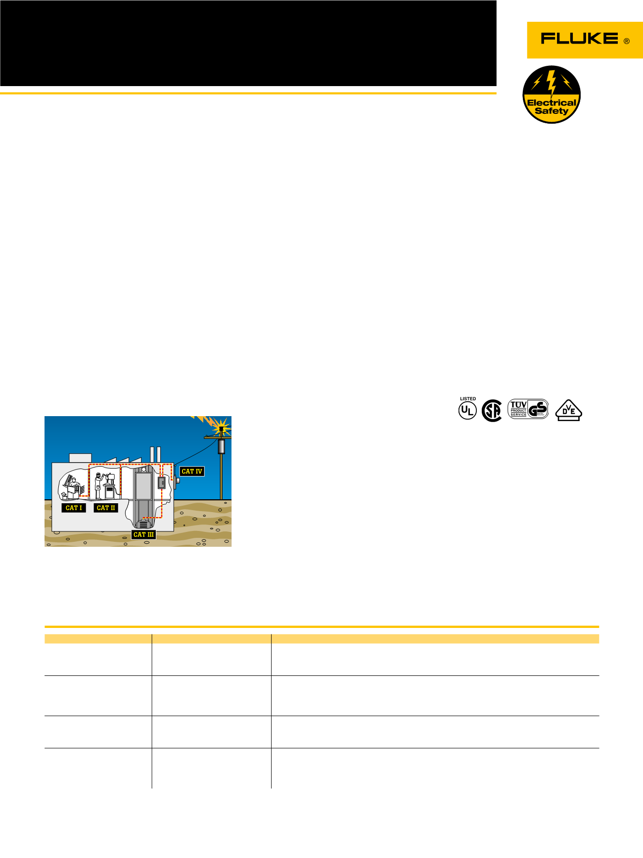
Figure 1. Understanding categories: location
Overvoltage installation categories. IEC 61010-1 applies to low-voltage (< 1000V) test equipment
Fluke: Where safety is built in
Overvoltage category
In brief
Examples
CAT IV
Three-phase at utility connection,
any outdoor conductors
• Refers to the “origin of installation”; i.e., where low-voltage connection is made to utility power.
• Electricity meters, primary overcurrent protection equipment.
• Outside and service entrance, service drop from pole to building, run between meter and panel.
• Overhead line to detached building, underground line to well pump.
CAT III
Three-phase distribution, including
single-phase commercial lighting
• Equipment in fixed installations, such as switchgear and polyphase motors.
• Bus and feeder in industrial plants.
• Feeders and short branch circuits, distribution panel devices.
• Lighting systems in larger buildings.
• Appliance outlets with short connections to service entrance.
CAT II
Single-phase receptable
connected loads
• Appliance, portable tools, and other household and similar loads.
• Outlet and long branch circuits.
• Outlets at more than 10 meters (30 feet) from CAT III source.
• Outlets at more than 20 meters (60 feet) from CAT IV source.
CAT I
Electronic
• Protected electronic equipment.
• Equipment connected to (source) circuits in which measures are taken to limit transient overvoltages
to an appropriately low level.
• Any high-voltage, low-energy source derived from a high-winding resistance transformer, such as the
high-voltage section of a copier.
As distribution systems and loads
become more complex, the possibilities
of transient overvoltages increase.
Motors, capacitors and power conversion
equipment such as variable speed drives
can be prime generators of spikes.
Lightning strikes on outdoor transmission
lines also cause extremely hazardous
high-energy transients. If you’re taking
measurements on electrical systems,
these transients are “invisible” and
largely unavoidable hazards. They occur
regularly on low-voltage power circuits,
and can reach peak values in the many
thousands of volts. To protect you against
transients, safety must be built into the
test equipment.
Who Develops Safety Standards?
The IEC (International Electrotechnical
Commission) develops international general
standards for safety of electrical equipment
for measurement, control and laboratory
use. IEC61010-1 is used as the basis for the
following national standards:
• US ANSI/ISA-S82.01-94
• Canada CAN C22.2 No.1010.1-92
• Europe EN61010-1:2001
Overvoltage Installation Categories
IEC61010-1 specifies categories of
overvoltage based on the distance the piece
of equipment is from the power source
(see Fig. 1 and Table 1) and the natural
damping of transient energy that occurs
in an electrical distribution system. Higher
categories are closer to the power source and
require more protection.
Within each installation category there are
voltage classifications. It is the combination of
installation category and voltage classification
which determines the maximum transient
withstand capability of the instrument.
IEC 61010 test procedures take into account
three main criteria: steady-state voltage,
peak impulse transient voltage and source
impedance. These three criteria together will
tell you a multimeter’s true voltage withstand
value.
Within a category, a higher working voltage
(steadystate voltage) is associated with a
higher transient, as would be expected. For
example, a CAT III 600 V meter is tested
with 6000 V transients while a CAT III 1000 V
meter is tested with 8000 V transients.
So far, so good. What is not as obvious is the
difference between the 6000 V transient for
CAT III 600 V and the 6000 V transient for
CAT II 1000 V. They are not the same. This is
where the source impedance comes in. Ohm’s
Law (Amps = Volts/Ohms) tells us that the 2 Ω
test source for CAT III has six times the current
of the 12 Ω test source for CAT II. The CAT III
600 V meter clearly offers superior transient
protection compared to the CAT II 1000 V
meter, even though its so-called “voltage
rating” could be perceived as being lower. See
Table 2.
Independent testing is the key to safety
compliance
How can you tell if you’re getting a genuine
CAT III or CAT II meter? Unfortunately it’s
not always that easy. It is possible for a
manufacturer to self-certify that its meter
is CAT II or CAT III without any independent
verification. The IEC (International
Electrotechnical Commission) develops and
proposes standards, but it is not responsible
for enforcing the standards. Look for the
symbol and listing number of an independent
testing lab such as UL, CSA, VDE, TÜV or other
recognized approval agency.
These symbols can only be used if the product
successfully completed testing to the agency’s
standard, which is based on national and
international standards. UL 3111, for example,
is based on EN61010-1. In an imperfect world,
this is the closest you can come to ensuring
that the meter you choose was actually tested
for safety.