


 104 / 164

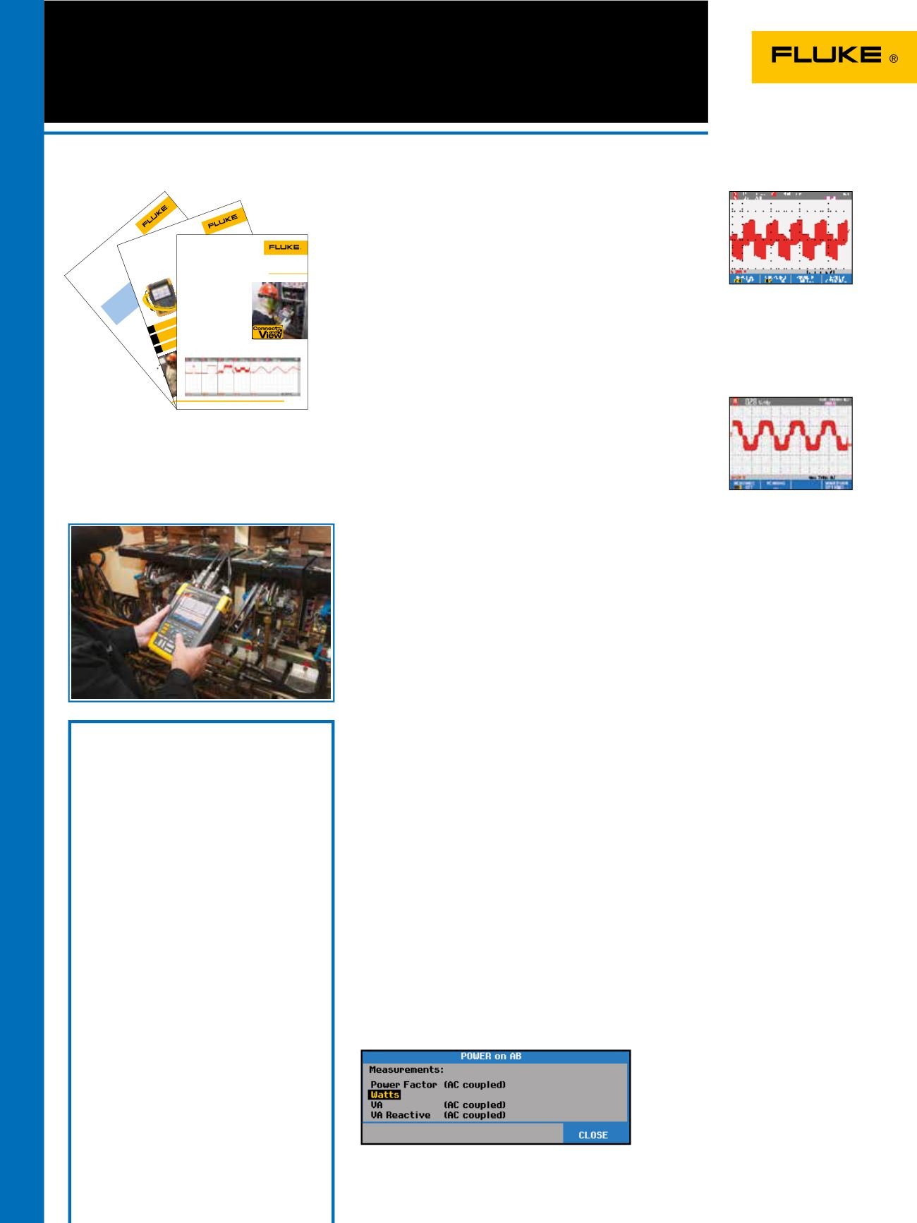
Figure 1.
G703 - E1 template
ApplicationNote
From the Fluke Digital Library @ www.fluke.com/library
TheG.703 standard
G.703 is a standard origi-
nally introduced for voice and
data transmission over digital
networks. It is an ITU recom-
mendation (formerly CCITT)
that’s associatedwith the PCM
standard. Analog-voice to digital-
data conversion according to
PCM requires a bandwidth of
64 kb/s (±100 ppm), resulting in
the basic unit forG.703. Through
multiplexing this results in a T1
of 1.544Mb/s and E1 of
2.048Mb/s.
The electrical characteristics
of the network interfaces are
described in recommendation
G.703. The signal limits for a
2.048Mb/s signal are shown in
Figure 1.
Multiple-channel
testing using two
differentmasks
A balun is used between the
patch panel and a coaxial
transmission line tomatch the
impedance of the 120
Ω
sym-
metrical line to a 75
Ω
coaxial
line. The input and output of the
balun each has its specificmask.
The ScopeMeter 190 Series II
portable oscilloscopes can simul-
taneously perform a pass/fail test
at the input and output of the
balunwith differentmasks.
The floating and isolated
inputs of the Fluke ScopeMeter
190 Series II test toolsmake
thesemeasurements pos-
siblewithout the risk ofmaking
unwanted groundings.Moreover,
the high impedance probes allow
for directmeasurementswithout
loading the line andwithout the
need for an external differential
probe.
Testing telecommunication
equipment using Pass/Fail
mask testing with a Fluke
ScopeMeter
®
190 Series II
Editing the pass/fail
templates
With FlukeViewwe can export
awaveform into a spreadsheet
and a custom template can be
created by editing awaveform
using Excel.
A reference template for
pass/fail testing can be cre-
ated by savingwaveforms from
FlukeView in .csv format and
editing thewaveform using, for
Figure 2.
ISDN30 network
ISDN30
Patch
Panel
Balun
SDH
Distr.
2Mb/s
120Ω
2Mb/s
120Ω
2Mb/s
75Ω
Telephone
Exchange
Nowadays digital communication systems such as Synchronous
DigitalHierarchy (SDH) in Europe and the SynchronousOptical
Network (SONET) inNorthAmerica require standard testmethods.
The electrical signals are tested against the standard ITU pulse
masks. The Fluke ScopeMeter 190 Series II portable oscilloscope
offers a standard pass/fail function that can be used to perform
these tests. The instrument is capable of storing up to 100 “fails”
for further analysis.
ApplicationNote
Demystifying
drive anomalies
using theFluke 190Series II2-Channel
ScopeMeter
®
portableoscilloscope
From the Fluke Digital Library @ www.fluke.com/library
Vogel, anHVAC technician,
becomes energizedwhen dis-
cussing the return on investment
in his handheld ScopeMeter
®
Test Tool. “Out at one large site,
wherewemonitor and trouble-
shoot variable frequency drives
(VFDs), component-level repair
can oftenmean the difference
between a $20 repair part and
a $100,000 repair bill. I know
firsthand, becausewe recently
documented that very scenario.”
On large VFDs, Vogel uses his
ScopeMeter portable oscilloscope
to uncover capacitance problems,
transistor firingmishaps, and
even bleed-throughs on a gate.
“Of course, a transistor is basi-
cally a lightning-fast switch,”
he says. “It switches back and
forth
between open and closed,
and itcan sometimes start to
break down.When that happens,
motorswill start doingweird
things. For example, at load
stagewe’ll actually see
themotor banging back and
forth as if it is not surewhich
way to turn.”
Seeing is believing?More aptly, seeing is
understanding.
If anyone canwring every last ounce of functionality out
of a piece of electronic test equipment, it’sChris Vogel.
At SiemensBuilding Technologies, Vogel has hiswork cut
out for him keepingHVAC systems running for the com-
pany’s large commercial customers in Florida’s tropical
weather,which ismarked by seemingly nonstop 90 °F
temperatures and 95% humidity levels.And that’s just
one of the challenges faced by technicians at Siemens
Building Technologies,which plays amore sweeping role
in its customers’ success: ensuring energy efficiency,
comfort, protection against unauthorized access, and
fire safety year-round for every building or office tower
entrusted to it by customers.
Storing a slice of time
It’s important, says Vogel,
that the technician be able to
characterize VFD problems by
capturing awaveform from the
offending drive.His premise: A
signal ismuchmore tellingwhen
presented in awaveform view
than in a single, static volt-
age reading. The signal has a
shape and value thatmay look
right at a glance, but could just
as easily have a distortion or
rough “edge,” or amomentary
spike almost too short to be
seen. Either problem, or a host
of other signal anomalies,would
be indistinguishablewith just a
numeric reading of the signal.
“The scope allowsme to
record information, and from a
number of sources—sinewaves
on the inputs and outputs of
VFDs, current and voltage—and,
for thatmatter,make compari-
sons of current and voltage so
that I can derive a power factor
for the circuit.”
Operator:
CrisVogel,HVAC
Technician forSiemensBuilding
Technologies
Testing
Functions
Case
Study
Measuring tools:
190 Series II
2-Channel
ScopeMeter
®
TestTool
Measurements:
Currentand voltage
waveform analysis, power factor
Connect the ScopeMeter
test tool and view the
result: the start of every
measurement
It frequently happens that service
engineers have to spend a lot of
time adjusting theirmeasuring
device such as a portabl oscil-
loscope for an optimal setting.
Valuable time is spent completing
this set up, and ideally, this could
be done automatically.
With the introduction of the
new ScopeMeter 190 Series II,
Fluke has revamped its unique
feature, Connect andView.
Scope users know how dif-
ficult triggering can be.Wrong
settings show unstable and
sometimeswrong results. Fluke’s
unique Connect andView
recognizes signalpatterns, and
automatically sets up correct
riggering, attenuator and time
base settings. Switcing on the
ScopeMeter portable oscilloscope
to display correct signal patterns
only takes a couple of seconds,
and this is exactlywhat an
oeratorwants.
Settings regarding
amplitude,
timebase,
triggering,
etc.
are automatically detected and
adjusted, followed by display-
ing the signal in the correct atio
with respect to the horizontal
and vertical axis.At least 1.5
t 4 perids of the signal are
measured before the pattern is
shown.
Connect andView provides
a stable, reliable and repeat-
able display of virtually any
signal, includingmotor drive and
controlsignals,without touch-
ing a button. Signal changs are
instantly recognized and settings
adjusted for, once again, a stable
display. This is all done auto-
matically, butmanual overruling
is still possible. Ifmanual over-
ruling is needed, the ScopeMeter
190Serieswill switch frm auto-
matic to 1/2 automatic,w ch is
visible on the display.
Figure 1 gives an example of
the diffrent ypes ofwaveforms
which can de detected by
Connect&View. If required the
criteria for best settings can be
optimizd by switching on one or
all of the following options:
Automatic trigger
ApplicationNote
From the Fluke Digital Library @
www.fluke.com/libraryFigure1.
AC/DC coupling
Glitch detect
Figure 2 shows the different
ettings.
100
ScopeMeter
®
Portable
Oscilloscopes 190 Series II
Application driven
Find problems in industrial systems including:
• Circuit voltage/current overloading
• Attenuation/input impedance mismatch
• Signal fluctuation/drift
• Conditioning circuits signal integrity
• Test point verification for critical signals
• Input/output/feedback timing issues
• Induced noise and disturbances
• Random shutdowns/reset
Diagnose VFDs* or power inverters
and converters
• Harmonics, transients and loads in three phase power input
• Troubleshoot dc to ac converters for faulty control circuits or
output IGBT gate stages
• Cable interface - test PWM output for reflections
and transients
• Vpwm measurement to measure the effective voltage on
drive outputs
• Determine V/Hz ratio to find outif that fits the specification
of the motor.
Applications made visible with
a simple push of a button.
Vpwm measurements
The output signal of a VFD is very complex. When selecting the
Vpwm function, the ScopeMeter automatically switches over to
a dedicated piece of software which is capable of analyzing the
waveform.
Volt/Herz ratio measurements
The output torque for a motor is determined on the basis of the
ratio of the motor’s applied voltage and frequency, known as
the Volts per Hertz (V/Hz) ratio. Failure to maintain the proper
ratio will have influences on the motor torque, the speed of
the shaft and the motor noise. Next to that the motor will
draw more current leading to an increased temperature. For a
motor to produce its rated torque at variable speeds, it also is
necessary to control the voltage and frequency supplied to the
motor. A VFD maintains a preset V/Hz ratio in supplying power
to a motor at the variable speeds. This critical V/Hz ratio can be
monitored by a special function which is part of the readings.
Power measurements
With today’s fluctuations on the power grid it is important
to get detailed information about parameters such as Power
Factor, VA and VA reactive. The ScopeMeter can measure these
factors with a push of the button.
A range of application notes is available.
See the Fluke website.
Included Accessories
Fluke 190 Series II 4-channel instruments include
a set of four probes, hanging strap, handstrap, USB
cable with mini-B connector, double capacity Li-ion
battery BP291, battery charger/power adapter BC190,
a FlukeView demo package and users manuals on
CD-ROM.
The 2-channel models come with two probes plus a
set of TL175 test leads and a single capacity battery
BP290.
The 190-504 also includes 4 pcs TRM50 coaxial
feedthrough terminator.
Ordering Information
Fluke-190-504
Color ScopeMeter (500 MHz, 4 channel)
Fluke-190-504/S Color ScopeMeter (500 MHz, 4 channel),
with SCC290-kit
Fluke190-502
Color ScopeMeter (500MHz, 2 Channel)
Fluke190-502/S Color ScopeMeter (500MHz, 2 Channel),
with SCC290-kit
Fluke-190-204 Color ScopeMeter (200 MHz, 4 channel)
Fluke-190-204/S Color ScopeMeter (200 MHz, 4 channel),
with SCC290-kit
Fluke-190-202 Color ScopeMeter (200 MHz, 2 channel)
Fluke-190-202/S Color ScopeMeter (200 MHz, 2 channel),
with SCC290-kit
Fluke-190-104 Color ScopeMeter (100 MHz, 4 channel)
Fluke-190-104/S Color ScopeMeter (100 MHz, 4 channel),
with SCC290-kit
Fluke-190-102
Color ScopeMeter (100 MHz, 2 channel)
Fluke-190-102/S Color ScopeMeter (100 MHz, 2 channel),
with SCC290-kit
Fluke-190-062 Color ScopeMeter (60 MHz, 2 channel)
Fluke-190-062/S Color ScopeMeter (60 MHz, 2 channel),
with SCC290-kit
For all optional accessories for the Fluke 190 Series, see page 102