
F4
F3
F2
F1
100.00°
C
F4
F3
F2
F1
266.03°
C
SETPT: 266.00 °C
TC—T : 265.783
°
C
HEAT: 22
•
/
•
•
Depending on the
thermocouple, incorrectly
setting reference junction
compensation may result
in a temperature error
of around 23 °C. Also,
the reference junction
compensation accuracy
of the meter may be the
largest contributor to
the error.
•
Thermocouple wire
generates a voltage
whenever two adjacent
points along the wire are at
different temperatures.
•
The whole length of the
wire (not just the probe
tip) generates the voltage.
This means the whole
wire needs to be treated
carefully and considered
during the calibration.
Additional resources
For more in depth information
about this application check out
these videos and application notes
from Fluke.
Thermocouple
Fundamentals
application note
TECH
TIPS
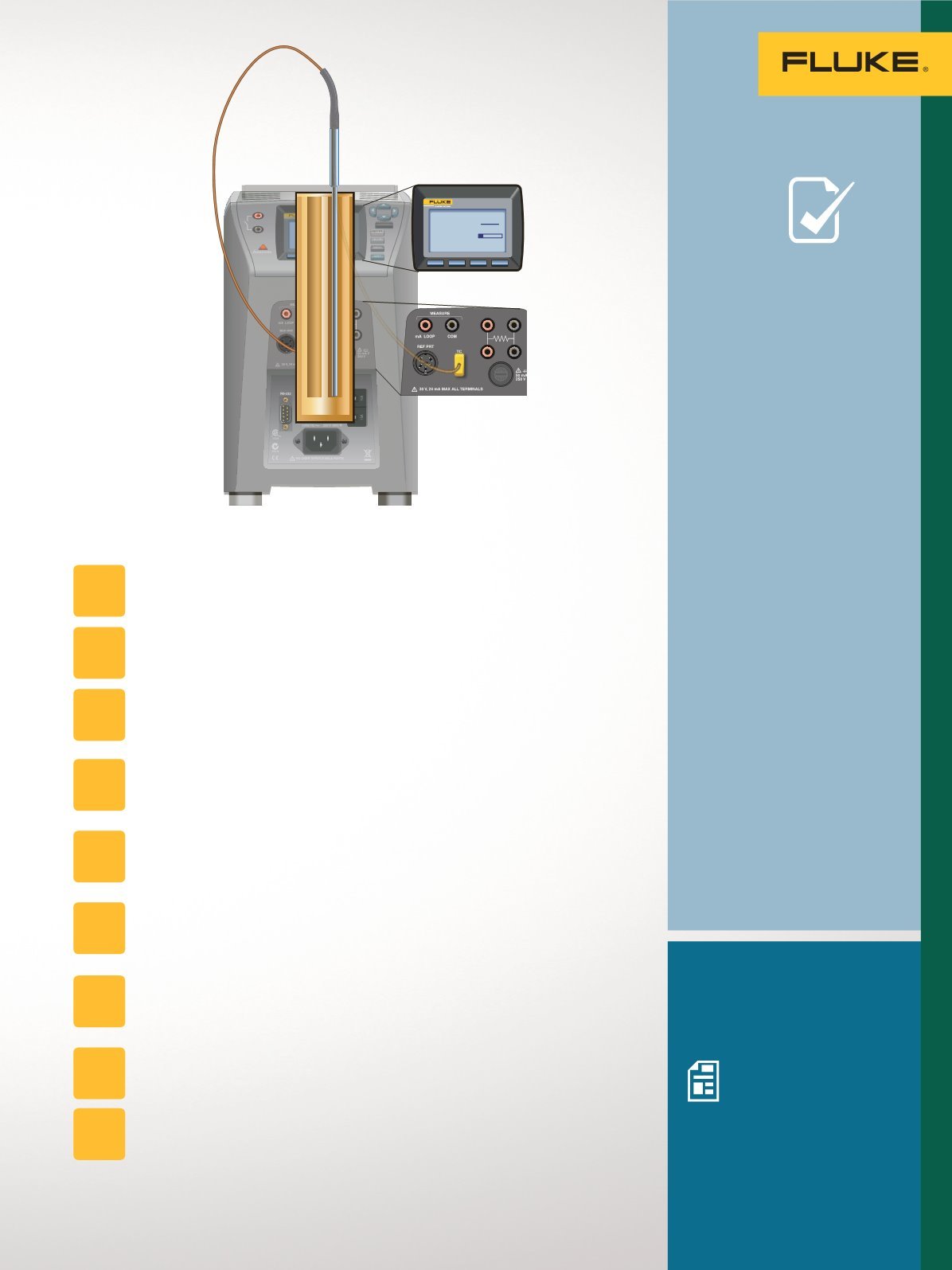
To perform the test:
Isolate the sensor from the process.
Fully immerse the sensor into a precision temperature source such as a
dry-well or bath capable of covering the required temperature range.
To check the calibration of the thermocouple separately from control
system temperature indicator, disconnect the thermocouple from
the electronics.
Connect the thermocouple to a precision instrument capable of measuring
millivolts. (The process version of Field MetrologyWells have the required
electronics built in.)
If the thermocouple has a reference junction (most do not), then ensure
that the reference junction is also immersed at the required reference
temperature. Usually, this is 0 °C.
Typically, the thermocouple will not have a reference junction. In that
case, ensure that the precision voltage measurement device has reference
junction compensation (may be identified as RJC or CJC) turned on.
Adjust the temperature of the bath or dry-well to each of the test points.
(With Field MetrologyWells these test points can be preprogrammed
and automated.)
At each test point record the readings of the temperature standard and
thermocouple.
If measuring the thermocouple separate from its measurement electronics,
compare the measured voltage to the expected voltage from the applicable
temperature table. Otherwise, compare the reading on the instrument display
to the reading of the temperature standard (which may be the dry-well).
STEP
1
STEP
2
STEP
3
STEP
4
STEP
6
STEP
8
STEP
9
STEP
7
STEP
5
49
Temperature Applications


