


 53 / 64

SAVE
NEXT
HOME
LOG
RESET
ENTER
RECALL
HOLD
STATS
°
C
°
F
SETUP
TREND
mV
RS
232
12
VDC
30
VMAX
T1
T2
1524
CALIBRATION
THERMOMETER
READOUT
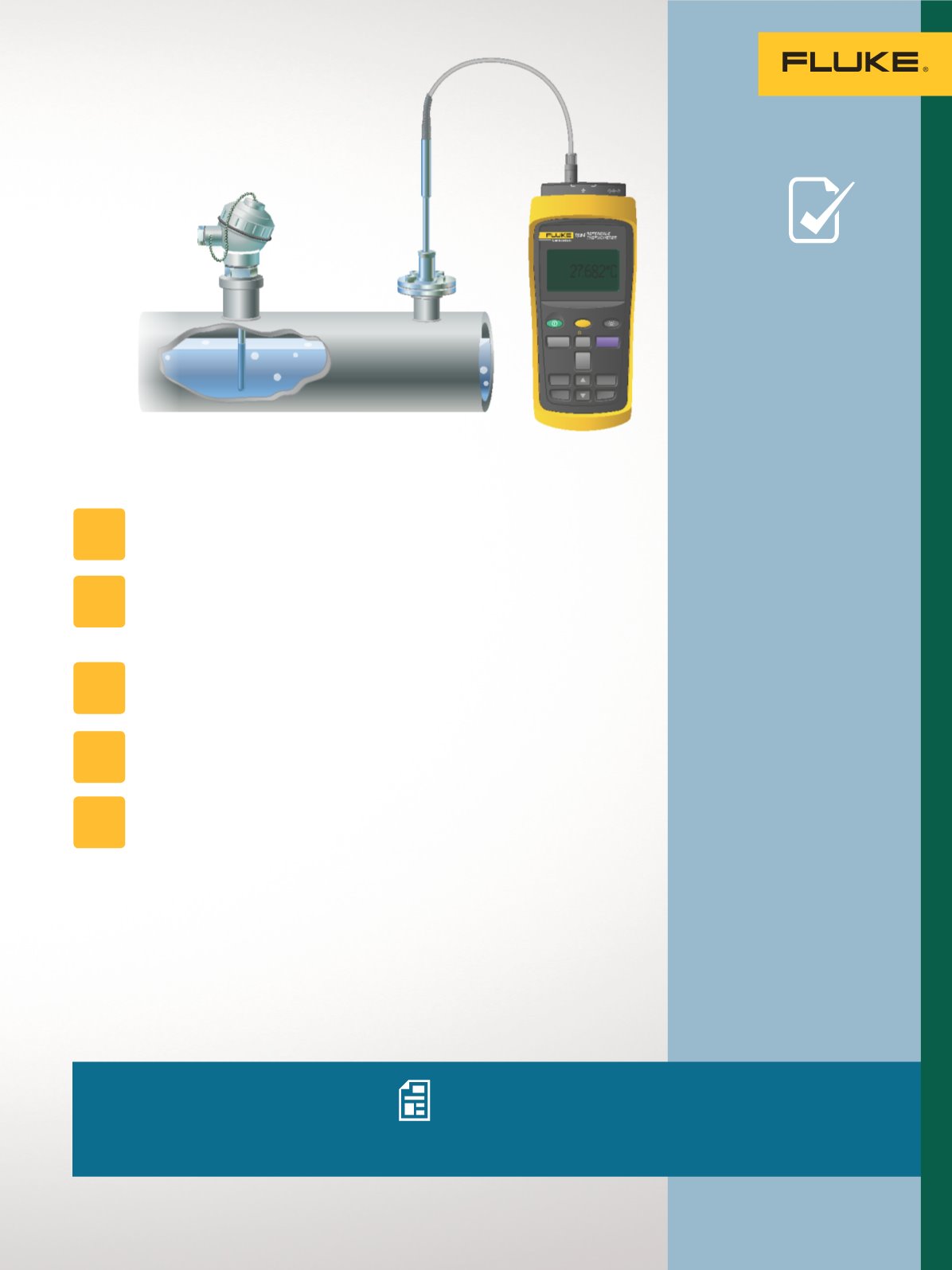
The test well (thermowell) should be within a few inches of the
temperature transmitter and sensor assembly to be tested.
Make sure that the probe of the temperature standard is long
enough to reach the bottom of the test well and that air gaps
between the probe and well are minimized.
Wait for the temperature standard to reach the temperature of
the test well. This will take a few minutes.
Check for temperature stability. A graphing digital thermometer
such as the 1524 makes stability easier to recognize.
Record the reading from the measurement system and the
temperature standard to determine whether the measurement
system’s readings are suspect.
•
For this type of application
a battery powered digital
thermometer is usually
preferred.
•
A graphing display helps
the technician visualize
trends such as stability
quickly and easily.
•
Ensure that both the probe
and the readout of your
temperature standard
have traceable calibration
certificates from a
competent laboratory.
•
If the probe and readout
separate from each other,
smart connectors, which
include probe calibration
constants, provide a
best practice method of
ensuring that the readout
is using the correct
probe calibration in its
temperature readings.
STEP
1
STEP
2
STEP
3
STEP
4
STEP
5
To perform the test:
Additional resources
For more in depth information about
this application check out these videos
and application notes from Fluke.
Temperature measurement and calibration:
What every instrument technician should know
Industrial temperature readout and probe
selection guide
Process Calibration Tools: Temperature Applications
TECH
TIPS
53
Temperature Applications