


 61 / 64

Additional resources
For more in depth information about
this application check out these videos
and application notes from Fluke.
Emissivity makes a difference
How to Calibrate an IR Thermometer
webinar
Infrared Temperature Calibration 101
application note
Infrared Thermometer Calibration – A Complete Guide
•
Emissivity makes a big
difference in infrared
temperature measurement.
•
The temperature and
emissivity of the 4180
and 4181 are calibrated
radiometrically for the
most reliable and
traceable results.
•
The Fluke 4180 and 4181
can be set to match the
emissivity setting of fixed
emissivity thermometers.
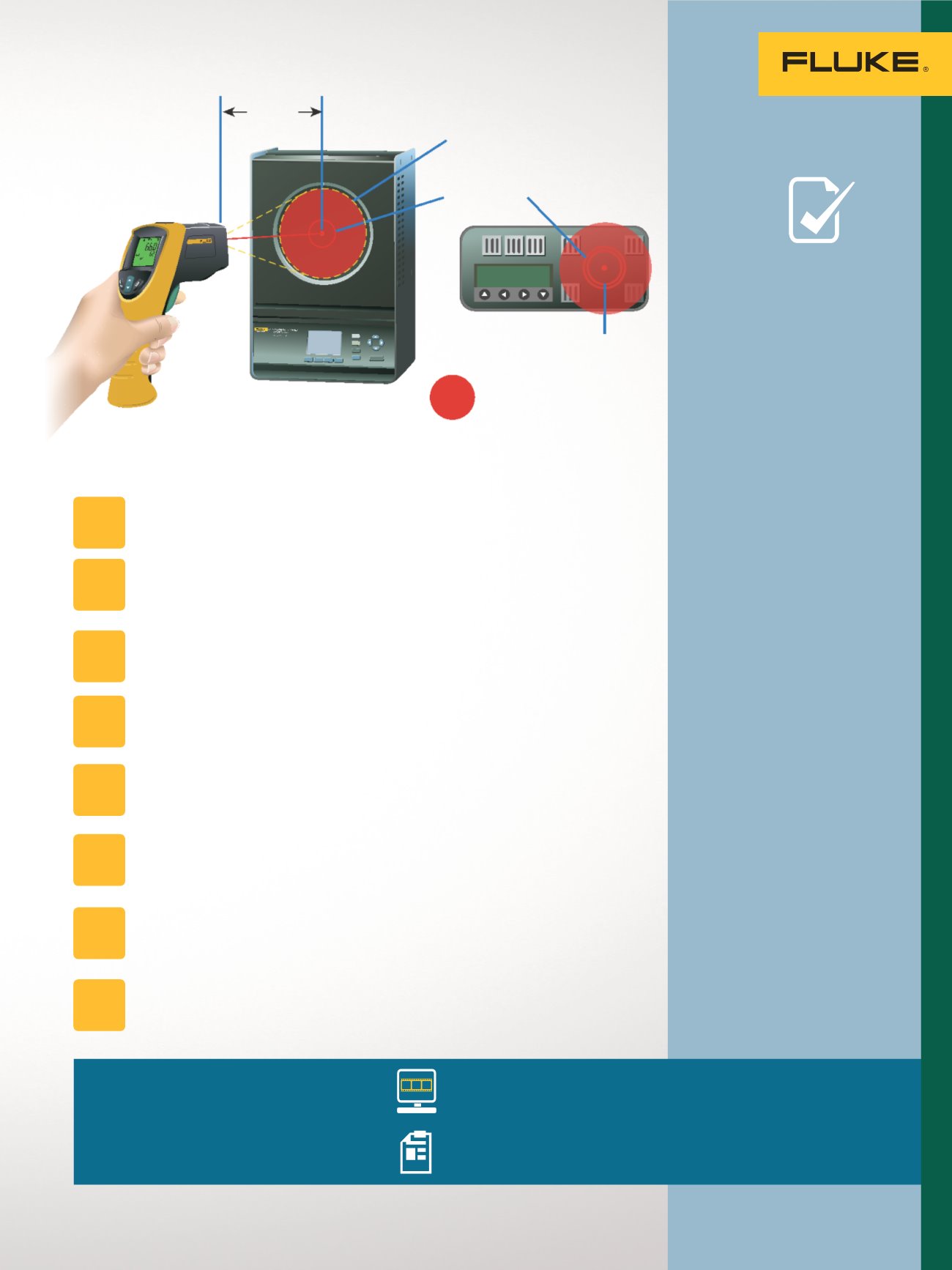
•
The large area of the 4180
and 4181 target allows
infrared thermometers
to be calibrated at the
recommended distance
without including
unwanted surfaces in the
field of view.
•
Use a mounting device such
as a tripod to maintain the
calibration distance.
•
Measure the calibration
distance from the flat plate
surface to the surface of
the front housing of the
infrared thermometer.
TECH
TIPS
To perform the test:
Allow at least 15 minutes for the IR thermometer to reach the
temperature of the shop or laboratory.
Set the radiation source to the desired calibration temperature.
Depending on the temperature range a low, high, and midpoint
temperature may be chosen.
If the infrared thermometer has an emissivity setting, it should be set to
match the calibrated emissivity of the source.
Position the infrared thermometer at the manufacturer’s recommended
calibration distance.
Center the infrared thermometer on the calibrator surface. Do this by
adjusting the aim slightly side to side and up and down to maximize
the signal.
The measurement time should be ten times longer than the infrared
thermometer’s response time. This is typically five seconds for Fluke
infrared thermometers.
Record the calibrator indicated reading and the indicated reading of
the thermometer under test to determine the error and tolerance status
of the thermometer at each set point.
Repeat for the other set point temperatures.
STEP
1
STEP
2
STEP
3
STEP
4
STEP
6
STEP
8
STEP
7
STEP
5
= IR thermometer field of view
Smaller target
Manufacturer
recommended
large target
IR thermometer
spot size
1 9 9 . 3
d
Measuring
(d) distance
561HVACPro
IRTHERMOMETER
61
Temperature Applications