


 63 / 64

•
Streamline the process with
automation and provide
documentation using a
Fluke 754.
•
Seventy-five percent of
the errors in a temperature
measurement system comes
from the sensor.
•
At minimum, you need a
calibrator, and a device
to measure 4-20 mA and
power the loop.
•
Choose a temperature
standard with a 90 degree
angle bend to ensure both
the temperature standard
and the transmitter fit in
the dry-well at the
same time.
Additional resources
For more in depth information
about this application check out
these videos and application notes
from Fluke.
TECH
TIPS
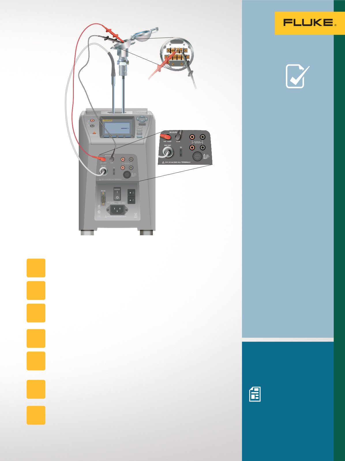
To perform the test:
Isolate the sensor from the process.
Fully immerse the sensor into a precision temperature source such as a
dry-well or bath capable of covering the required temperature range.
Connect the temperature standard and 4-20 mA output of the
transmitter to a suitable meter or calibrator (for example, the process elec-
tronics on a Fluke Field MetrologyWell or the inputs of a Fluke 754).
Power the loop. (The Fluke 754 and the process electronics in a
Field MetrologyWell have this capability.)
Adjust the temperature of the bath or dry-well to each of the test points.
(With Field MetrologyWells, these test points can be preprogrammed
and automated.)
At each test point, monitor and record the readings of the
temperature standard and the local or remote readings connected
to the transmitter output.
Also, record the 4-20 mA output of the transmitter to determine which
device needs adjustment if an adjustment is required.
STEP
1
STEP
2
STEP
3
STEP
4
STEP
6
STEP
7
STEP
5
Eliminating Sensor
Errors in Loop Calibrations
Multifunction calibration
using the 7526A Precision
Process Calibrator
Improving loop calibration
temperature accuracy
F4
F3
F2
F1
100.00°
C
TESTDCPWR
++–
–
63
Temperature Applications